EIGRP Unequal Cost Load Balancing
Depending where you are in your studies, unequal cost load balancing can mean very different things. It is one of the factors that separates EIGRP from other routing protocols and initially one of the things that really piqued my interest.
When preparing for your CCNA, you learned all routing protocols can load balance (normally 4 paths by default) and that EIGRP is the only routing protocol that can perform unequal cost load balancing. That is pretty much where your understanding will end at the associate level.
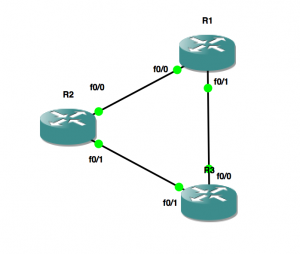
Here is what equal cost load balancing looks like:
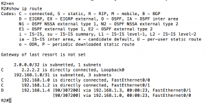
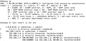
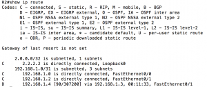
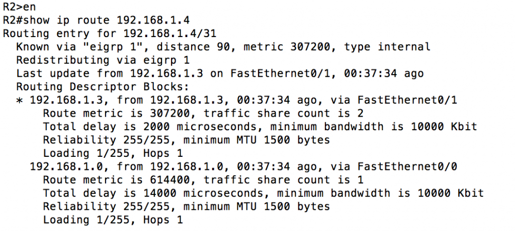
From R2 (assuming links are all the same speed and type) the link between R1 and R3 (192.168.1.4/31) is equidistant. A look at the routing table will confirm:
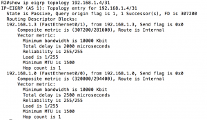
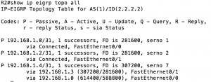
What we’ve seen is simple equal cost load balancing, something any routing protocol can do. At the CCNP level, we learn in order to turn on unequal cost load balancing we use the “variance” command. The number after the “variance” command is the multiple of the feasible distance. For instance “variance 2” would load balance across paths up to twice the value of your successor route (our successor above is 307200, so it would take up to 614400). By going into R1 and changing the delay on fa 0/1 to a higher value (“delay 150” would change the delay from 1000 microseconds to 1500 microseconds) R2 will stop load balancing and start using R3 for the 192.168.1.4/31 network. A professional level task would be to allow R2 to load balance the 192.168.1.4/31 network. To accomplish this we need to find out how much worse the path through R1 is than the path through R3. Using “show ip eigrp topology 192.168.1.4/31” we can easily find this out:
From the command output, we can tell our successor is 307200 (route through R3) and our feasible successor is 320000 (route through R1). A variance of 2 would easily cover this. Here is what that would look like:
The first screenshot shows the variance command. The second screenshot confirms via the routing table that we are unequal cost load balancing. You can tell you are unequal cost load balancing because the metric for each path is different. The third screenshot tells us HOW we are actually load balancing. The “traffic share count” value tells us how the packets will be sent out. In this case for every 47 packets, 24 will use R3 where 23 will use R1. This is where the professional level understanding stops.
To bump things up to the expert level we are going to control the ratio of packets sent to R1 and R3. This is where things get scary because the math starts now. The formula for the composite metric is:
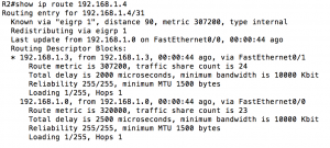
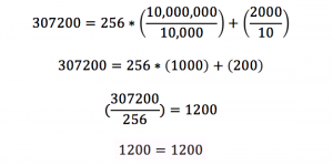
Lets try running through the equation once to prove it actually works. Reference back to the “show ip route 192.168.1.4/31” output to see where I got the values for composite metric, lowest bandwidth and sum of delay. Here is what that would look like:
So now that we’ve proven the equation works (and the router can do math), let’s talk about how we can use this. Maybe we have a MRC-142 link operating at 8Mbps and a Phoenix link operating at 4Mbps to connect two sites together. Without changing anything the default serial bandwidth and delay would be equal and you would equal cost load balance. When you start manipulating the bandwidth and delay values you need to be careful. The bandwidth value has other dependencies (namely QoS) so that needs to accurately match the actual link bandwidth. Plus given the example provided, if you typed “bandwidth 8000” and “bandwidth 4000” it would not load balance at a 2:1 ratio (see equation).
So given it is best to not change bandwidth from the accurate value if you can help it, we need to tweak the equation so we can find out what we need to change the delay to (x will represent the value that needs to be added to the total delay). Let’s take our previous example and topology and see if we can get a 2:1 ratio. I’m going to go back on the interfaces and set the bandwidth and delay values back to default. For the purposes of this example, we want a 2:1 ratio for our load balancing. The ratio is based off of the metric value, so we need the metric value to be half as good as our primary path (twice the value). It would look like this:
Let’s solve the equation and see how we would add the additional delay. Solving the equation would look like this:
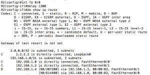
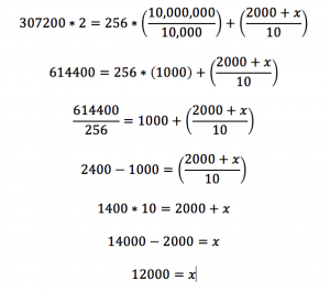 So now that we know what we need to add to our delay we verify the current delay on the interface (1000 microseconds on R1 fa 0/1) so we would issue the command “delay 1300” (delay command is 10s of microseconds). After the command is issued we will head back to R2 and verify it worked. A quick “show ip route” should do the trick:
Hmm, no load balancing. What gives? Let’s check the topology table, maybe we made a math error.
The metric value is exactly what we wanted it to be. So what gives? Said another way, what is one of the checks EIGRP performs to ensure there are no loops? Before this route could be installed the feasibility condition is checked. Because the advertised distance (588800) for R1 is greater than the feasible distance (307200) for R3 this won’t work. This path would still be used if the route to R3 goes down, but because of the feasibility condition we can’t load balance. Is there any way to get this to pass the feasibility condition? If we changed the delay on R2 instead of R1 that would not affect the advertised distance, so let’s try that.
From the above you can see that setting the delay back to default on R1 and making the change on R2 fixed the feasibility condition failure. Let’s make sure we satisfied the requirement for 2:1 load balancing:
That confirms it. The changes we made brought us to the required 2:1 ratio. Hopefully it is clear now how to manipulate your traffic to achieve the ratio you would like based on your requirements. It should also be clear that you need to be very careful not only which values you manipulate, but also where you manipulate them because there can be unintended or unexpected results.
